
10 H-Beam Sections + 3 Bracing Types: Q355B Roof Frame, L90×6 X-Braces, Φ133×4 Rigid Ties, L70×5 Knee Braces
2026-11-20 21:19:06






10 H-Beam Sections + 3 Bracing Types: Q355B Roof Frame, L90×6 X-Braces, Φ133×4 Rigid Ties, L70×5 Knee Braces
English Version
Title: Steel Roof Bracing System — 5 Q355B Frame Beams, 5 Secondary Beams, L90×6 X-Braces, Φ133×4 Ties, L70×5 Knee Braces
Data note: sections and grades are read from the two member section tables and the roof framing / bracing plans. Beam and brace lengths are not listed on these drawings; section weights below are theoretical values derived at 7,850 kg/m³.
Overview
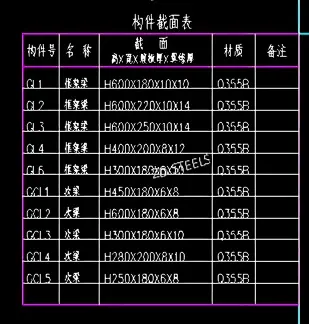
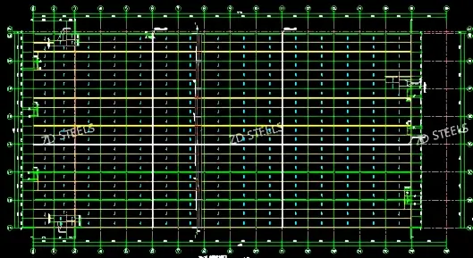
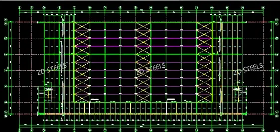
This is the roof framing and bracing system of a steel frame. Five frame beam sections and five secondary beam sections carry gravity loads; three bracing members stabilize the roof plane: X-shaped horizontal braces, rigid tube ties, and knee braces. Frame members are Q355B; bracing members are Q235B. The plans show a regular column grid with braced bays at set positions between axes 1–16.
Frame and Secondary Beams (Q355B)
表格
| Member | Name | Section H×B×tw×tf (mm) | Grade |
|---|---|---|---|
| GL1 | Frame beam | H600×180×10×10 | Q355B |
| GL2 | Frame beam | H600×220×10×14 | Q355B |
| GL3 | Frame beam | H600×250×10×14 | Q355B |
| GL4 | Frame beam | H400×200×8×12 | Q355B |
| GL6 | Frame beam | H300×180×6×10 | Q355B |
| GCL1 | Secondary beam | H450×180×6×8 | Q355B |
| GCL2 | Secondary beam | H600×180×6×8 | Q355B |
| GCL3 | Secondary beam | H300×180×6×10 | Q355B |
| GCL4 | Secondary beam | H280×200×8×10 | Q355B |
| GCL5 | Secondary beam | H250×180×6×8 | Q355B |
Bracing Members (Q235B)
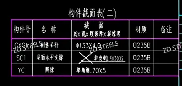
| Member | Name | Section | Grade | Ref. weight |
|---|---|---|---|---|
| GXG1 | Rigid tie (刚性系杆) | CHS Φ133×4.0 | Q235B | ≈12.6 kg/m |
| SC1 | Roof horizontal brace | Single angle L90×6 | Q235B | ≈8.4 kg/m |
| YC | Knee brace (隅撑) | Single angle L70×5 | Q235B | ≈5.4 kg/m |
The bracing plan shows three X-brace panels running across the roof grid; rigid ties connect brace nodes along the beam line; knee braces sit between secondary members and main frame.
How the System Works
- Frame beams carry gravity. GL sections span between columns and carry roof reaction from the secondary beam grid.
- Secondary beams spread the roof load. GCL members distribute purlin and panel loads to the frame beams.
- SC1 X-braces stabilize the roof plane. Crossed L90×6 angles transfer wind and longitudinal forces to the braced bays and down to the foundations.
- GXG1 ties hold the grid. The Φ133×4 rigid tube keeps beam spacing and brace node positions fixed, and acts as a compression tie in the bracing system.
- YC knee braces prevent lateral buckling. L70×5 angles brace the compression flange of beams and secondary members before roof sheeting is fixed.
Advantages
- Efficient X-bracing — crossed angles carry wind and longitudinal load with simple gusset nodes.
- Rigid tube ties — CHS ties keep the grid stable in both tension and compression and hold brace nodes in place.
- Knee braces stabilize beam flanges — YC angles reduce lateral torsional buckling before the deck diaphragm acts.
- Two-grade steel balance — Q355B for load-carrying beams, Q235B for bracing, keeps material cost matched to function.
- Standard sections — H sections, equal angles and CHS are common stock; shop fabrication and bolted erection are straightforward.
Disadvantages / Limits
- Angle brace capacity — single angles act mainly in tension; compression performance and slenderness must follow the design.
- Braced bays block routing — X-braces occupy selected roof bays; ducts, vents and openings must be coordinated around them.
- Gusset node work — brace ends need cut angles, gusset plates and drilled holes; fit-up affects bolt contact.
- Field alignment matters — brace length, angle and node position must match the as-built frame; mismatched braces introduce unintended prestress.
- Painting access — angle toes, heel welds and bolt holes in the roof plane need surface preparation and touch-up after erection.
Typical Use Cases
- Portal-frame warehouses and production sheds with purlin roof grids.
- Multi-bay industrial steel buildings needing lateral stiffness in the roof plane.
- Long-span frame roofs where X-braces transfer wind load to braced bays.
- Steel structures with equipment or duct runs that leave clear bays for bracing.
- Retrofit projects where an existing frame needs additional longitudinal and wind bracing.
Fabrication and Erection Notes
- Check mill certificates: Q355B for GL/GCL beams, Q235B for GXG1, SC1 and YC.
- Cut SC1 L90×6 and YC L70×5 to the brace angles shown; drill gusset holes to the node detail.
- Fabricate GXG1 Φ133×4 ties with end plates; check straightness before delivery.
- Erect frame and secondary beams first, install bracing and rigid ties before fixing roof sheeting.
- Check brace symmetry and bolt torque; do not leave an unbraced frame standing temporarily.
- Touch up damaged paint at holes, toes and field welds; provide corrosion protection per the building specification.
Bottom Line
A steel roof framing and bracing system: ten Q355B H-beam sections carry gravity, L90×6 X-braces stabilize the roof plane, Φ133×4 rigid ties hold the grid, and L70×5 knee braces stabilize beam flanges. The section split matches load to grade, and all members use standard sections. Member lengths, bolt counts and total weights come from the original framing drawings.
**WhatsApp**: +86‑13889862778, +86‑18242444407
**Email**: eddie@zdsteels.com, wells@zdsteels.com
YOU MAY LIKE