
24.8 m Curved Span, 10.3 m Twin-Cell Box Expressway: 1.6 m Deep Section, 5% Cross Fall, 100 mm Asphalt Deck
2026-11-22 22:11:16






24.8 m Curved Span, 10.3 m Twin-Cell Box Expressway: 1.6 m Deep Section, 5% Cross Fall, 100 mm Asphalt Deck
English Version
Title: Steel Box-Girder Expressway Bridge — 24.4–24.8 m Curved Span, 10.3 m Deck Width, 7.3 m Bottom Width, 1.6 m Depth, Twin-Cell Section, 80 mm C50 Base + 100 mm Asphalt
Drawing note: dimensions come from the standard cross-section (1:75) and the span-2 top-slab top-layer rebar plan (1:100). This batch does not list steel grade, plate thickness, member weight, bearing type or live load; those remain on the original structural drawings.
Overview
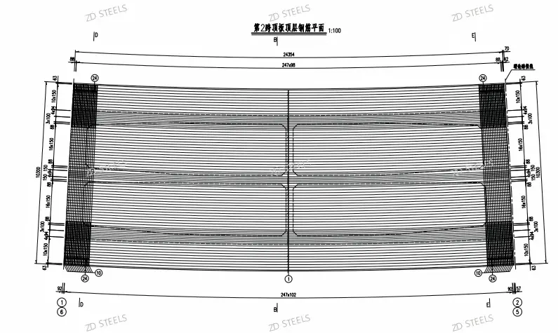
This is a box-girder bridge for an expressway alignment. The standard section is a twin-cell box 10,300 mm wide over a 9,300 mm carriageway, 7,300 mm bottom width and 1,600 mm depth, with 1,500 mm cantilevers each side. The span-2 top slab is laid out to a curved alignment: inner edge 24,354 mm, outer edge 24,798 mm. The deck build-up is 80 mm cast-in-place C50, a waterproof layer and 100 mm asphalt concrete, with a 5% cross fall.
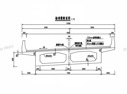
Standard Cross-Section Data (1:75)
| Item | Value |
|---|---|
| Overall deck width | 10,300 mm; carriageway 9,300 mm; edge 500 mm each |
| Half-widths | 5,300 + 5,000 mm |
| Bottom width | 7,300 mm; 500 + 2,900 + 500 + 2,900 + 500 |
| Cantilever | 1,500 mm each side |
| Section depth | 1,600 mm; tip 200 mm; root 450 mm |
| Slab thickness | 250 mm |
| Cell chamfer | Left 800×200; right 250×250 |
| Cross fall | 5% |
| Centerline offset | Box centerline 150 mm from road design line |
| Deck build-up | 100 mm asphalt + waterproof layer + 80 mm cast-in-place C50 |
Span-2 Top-Slab Rebar Plan (1:100)
表格
| Item | Value |
|---|---|
| Plan title | Span 2 top slab, top-layer reinforcement |
| Curved edge lengths | Inner 24,354 mm; outer 24,798 mm |
| Transverse width | 10,300 mm |
| End closure zones | 10×150, then 3×100 spacing; bars marked 24 and 10 |
| Midspan spacing | 16×150 |
| Distribution bars | 4φ4 (diameter per original bar schedule) |
| End condition | Theoretical expansion joint at axis E |
| Internal outlines | Four rounded-corner openings / diaphragm positions in the slab |
How the Bridge Works
- Box girder carries traffic loads. The twin-cell box resists bending, shear and torsion between bearings.
- Top slab distributes wheel load. Top-layer bars run along and across the slab; denser spacing at end zones matches higher local moments.
- Curved layout matches the alignment. Inner and outer edge lengths differ (24,354 / 24,798 mm); the slab and reinforcement follow the curve.
- Cantilevers narrow the superstructure. 1,500 mm side cantilevers carry sidewalk/edge strips and keep the box bottom to 7,300 mm.
- Deck layers protect the box. C50 base, waterproof membrane and asphalt separate traffic wear from the top plate.
Advantages
- Wide single section — 10.3 m deck fits a two-way carriageway with edge strips in one box.
- Shallow 1.6 m depth — reduces approach embankment height and works under limited clearance.
- Twin-cell torsion stiffness — suited to curved expressway ramps and skew crossings.
- Dense end reinforcement — bar spacing steps down at ends to cover support and joint regions.
- Protected deck — C50 base, waterproofing and asphalt limit steel exposure to moisture and wear.
Disadvantages / Limits
- Closed-box inspection — hatches, drainage and ventilation must be planned before the section closes.
- Curved fabrication — differential edge length and camber require curved setting out; straightening the box weakens the alignment.
- Waterproofing is critical — a broken membrane reaches the top plate; joints and edges need continuous protection.
- End and joint detail — bars at theoretical expansion joints, anchor blocks and bearing zones need the connection drawings; bar sizes in this plan are partly illegible.
- Data gaps on these drawings — steel grade, plate thickness, girder weight, span-by-span layout, bearing and pier data are not listed; capacity needs the original design.
Typical Use Cases
- Expressway mainline viaducts crossing roads, rivers and railway corridors.
- Interchange ramps and curved flyovers where a torsion-stiff box follows the radius.
- Urban elevated roads with limited ground clearance and tight right-of-way.
- Highway crossing bridges over existing roads or channels at skew or curved angles.
- Retrofit expressway additions where prefabricated box segments fit live-traffic erection windows.
Fabrication and Erection Notes
- Set out the curved box from the road design line; check inner/outer edge lengths 24,354 / 24,798 mm and the 150 mm centerline offset.
- Verify section dimensions: 10,300 mm width, 7,300 mm bottom, 1,600 mm depth, 250 mm slab.
- Lay top-layer rebar to the plan: 10×150 and 3×100 at end zones, 16×150 at midspan; confirm bar diameters against the bar schedule.
- Build the deck in sequence: 80 mm C50 base, curing, waterproof membrane, 100 mm asphalt; maintain the 5% fall.
- Check expansion-joint setting out at axis E and bearing regions before closing the box.
- Reserve internal access, drainage and coating touch-up at contact and weld areas.
Bottom Line
A twin-cell box-girder expressway bridge: curved span 24,354 / 24,798 mm, 10.3 m deck, 7.3 m bottom, 1.6 m depth, 250 mm slab, 5% cross fall, C50 base plus 100 mm asphalt. The rebar plan densifies spacing at end zones; dimensions and reinforcement come from the drawings, while steel grade, plate thickness, weights and bearings follow the original structural design.
**WhatsApp**: +86‑13889862778, +86‑18242444407
**Email**: eddie@zdsteels.com, wells@zdsteels.com
YOU MAY LIKE