
9 Q235B Tube Sections, 1,400 mm Grid, 6.3 m Axial Bay: Steel Platform with 300×200×8 Frame Beams and 200×12 Columns
2026-11-22 22:05:14






9 Q235B Tube Sections, 1,400 mm Grid, 6.3 m Axial Bay: Steel Platform with 300×200×8 Frame Beams and 200×12 Columns
English Version
Title: Structural Steel Platform — 9 Q235B Hollow Sections, GKL1 300×200×8 Frame Beam, GKZ1 200×12 Column, 1,400 mm Beam Spacing, 6,300 mm Bay
Drawing note: member grades and sections are read from the member material list; plan spacing from the C-C section and standard plan. The drawings do not list platform elevation, live load, deck plate thickness, member lengths, weights or foundation type; these remain on the original design.
Overview
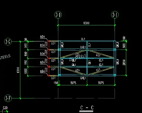
This is a welded rectangular-tube steel platform, all members in Q235B. A GKL1 perimeter frame of 300×200×8 rectangular tube carries GL1 secondary beams on a 1,400 mm spacing; GKZ1 200×12 square-tube columns support the frame. The C-C bay measures 6,300 mm on axis, divided into 3,075 + 3,075 with a 150 mm edge. Diagonal braces in LG1 stabilize the panel; LG2/LG3/LG4/LG5 cover edge beams, railing and stair connections.
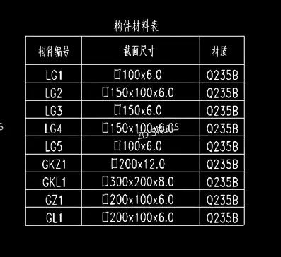
Member Schedule (Q235B)
| Mark | Section | Role |
|---|---|---|
| GKZ1 | □200×12.0 square tube | Main frame column |
| GKL1 | □300×200×8.0 rectangular tube | Frame beam |
| GZ1 | □200×100×6.0 rectangular tube | Secondary column |
| GL1 | □200×100×6.0 rectangular tube | Platform secondary beam / diagonal brace |
| LG2 | □150×100×6.0 rectangular tube | Edge / stair beam |
| LG4 | □150×100×6.0 rectangular tube | Edge / stair beam |
| LG3 | □150×6.0 square tube | Edge member |
| LG1 | □100×6.0 square tube | Railing / light brace |
| LG5 | □100×6.0 square tube | Railing / light brace |
Plan Dimensions
表格
| Item | Value |
|---|---|
| C-C bay, axial | 6,300 mm; interior 3,075 + 3,075; edge 150 mm |
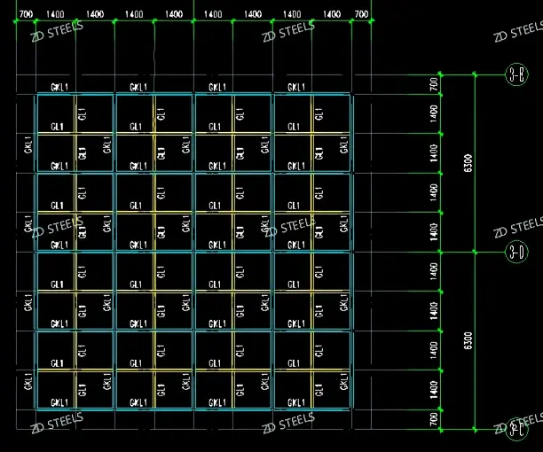
| Secondary beam spacing | 1,400 mm (standard plan) |
| Edge cantilever | 700 mm each side |
| Edge bands (C-C, side) | 100 / 900 / 2,850 / 900 mm |
| Outer stair-side bands | 50 / 900 / 950 / 950 / 1,000 mm |
| Axes shown | 3-1, 3-G, 3-F, 3-B, 3-D, 3-C |
How the Platform Works
Frame beams span between columns. GKL1 300×200×8 forms the perimeter and main bays; it carries secondary beams to the columns.
Secondary beams carry the deck. GL1 200×100×6 runs at 1,400 mm spacing and distributes deck load to the frame.
Columns transfer load to the base. GKZ1 200×12 main columns and GZ1 secondary columns take frame reactions to foundations.
Diagonals resist lateral load. LG1 diagonal braces in the panels stabilize the platform against wind and installation shifts.
Edge members finish the perimeter. LG2/LG4 edge beams, LG3 square tube and LG1/LG5 railing tubes close the sides and stair opening.
Advantages
Prefabricated tube construction — hollow sections shop-fabricated, bolted or welded on site; fast erection.
Regular 1,400 mm grid — repetitive beam bays simplify detailing, deck layout and future openings.
Light section range — 6–12 mm wall thicknesses match each member's role; no oversized steel.
All one grade, Q235B — procurement and welding qualification are consistent across the platform.
Open framing — easy to run pipes, cable trays and maintenance access under the deck.
Disadvantages / Limits
Deck system unspecified here — tread plate, grating or concrete fill and its thickness are not on these drawings; deck span capacity must be checked separately.
Lateral stability depends on braces and columns — diagonal layout and column base fixity control sway; weak bases or omitted braces reduce rigidity.
Hollow-section corrosion — enclosed tubes need drainage seals and edge coating; exposed platforms need scheduled repainting or galvanizing.
Connection design not detailed here — bolt size, weld size, base plate and anchor bolts are not listed; joints need the connection drawings.
Load data missing — platform live load, equipment load and impact load are not stated; member sizes must be verified against the actual design loads.
Typical Use Cases
Industrial maintenance and inspection platforms along production lines, tanks or equipment.
Pipe rack and cable-tray support platforms in plants, refineries and power stations.
Building mezzanines for storage, offices or auxiliary equipment over ground-floor space.
Stair and access tower landings connecting stairs at intermediate levels.
Temporary or permanent viewing and working platforms in commercial venues, stadiums and transport hubs.
Fabrication and Erection Notes
Verify Q235B mill certificates for all square and rectangular tubes.
Lay out the 1,400 mm secondary beam grid from the frame centerlines; check the 6,300 mm bay and 700 mm edge cantilever.
Match GKL1 300×200×8 to main spans, GKZ1 200×12 to main columns; do not substitute lighter sections without design review.
Weld or bolt braces before loading the frame; check diagonal alignment in each panel.
Seal tube ends and drill drainage holes where tubes are exposed; coat edges and contact surfaces.
Confirm deck type, railing height and stair connection against the general arrangement before handover.
Bottom Line
A Q235B steel platform built from nine tube sections: 300×200×8 frame beams, 200×12 main columns, 200×100×6 secondary beams on a 1,400 mm grid, 6,300 mm axial bay with 700 mm edge cantilevers, and LG-series edge, railing and brace tubes. Sections and spacing come from the drawings; elevation, loads, deck plate and connections follow the original structural design.
**WhatsApp**: +86‑13889862778, +86‑18242444407
**Email**: eddie@zdsteels.com, wells@zdsteels.com
YOU MAY LIKE