
411.3 t Q355MD Steel–Concrete Composite Box Girder: 10.3 m Wide Twin-Cell Section, 1.6 m Deep, 48 Bolts, 3,258 m² Internal Coating
2026-11-21 23:35:02






411.3 t Q355MD Steel–Concrete Composite Box Girder: 10.3 m Wide Twin-Cell Section, 1.6 m Deep, 48 Bolts, 3,258 m² Internal Coating
English Version
Title: Steel–Concrete Composite Box Girder Bridge — 411.3 t Q355MD Steel Plate, 10.3 m Deck, Twin-Cell Box 7.3 m Bottom Width, 1,476 kg Shear Studs, 3,258 m² Inner Coating
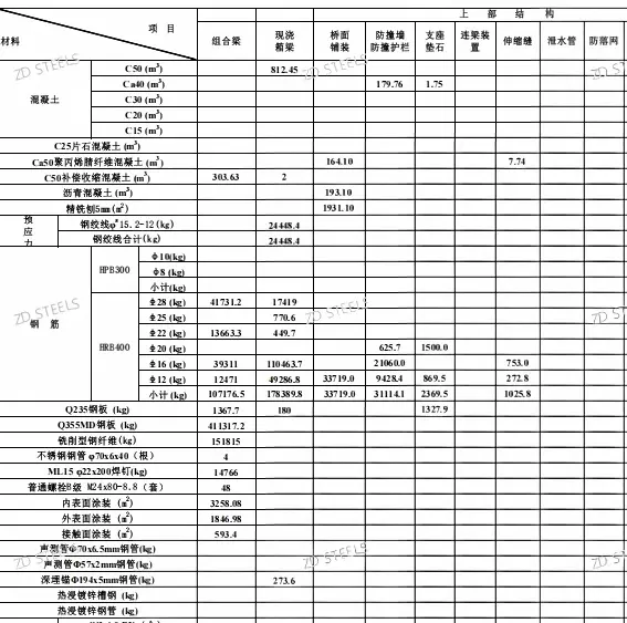
Drawing note: the material table splits the superstructure into a composite girder and a cast-in-place concrete box girder. The steel subject below is taken from the composite-girder column (Q355MD plate); the standard cross-section is taken from the standard cross-section drawing. Concrete box-girder items (C50 812.45 m³, prestressing strand 24,448.4 kg) are concrete members and are listed separately, not as steelwork. Span length and bearing size are not given on these drawings.
Overview
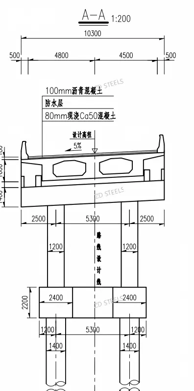
The composite superstructure uses a welded Q355MD steel box paired with a C50 compensated-shrinkage concrete deck. The standard section is a twin-cell box: overall deck width 10,300 mm, bottom width 7,300 mm, depth 1,600 mm, with 1,500 mm cantilevers on each side. Shear studs connect the steel top flange to the concrete slab; three coating zones are measured separately inside, outside and on contact surfaces.
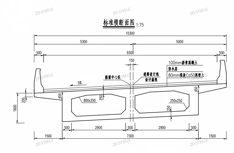
Standard Cross-Section (1:75)
| Item | Value |
|---|---|
| Overall deck width | 10,300 mm; carriageway 9,300 mm; edge 500 mm each |
| Bottom width | 7,300 mm; 500 + 2,900 + 500 + 2,900 + 500 |
| Cantilever | 1,500 mm each side |
| Section depth | 1,600 mm; cantilever tip 200 mm; root 450 mm |
| Top / bottom slab thickness | 250 mm |
| Cell chamfer | Left 800×200; right 250×250 |
| Cross fall | 5% |
| Centerline offset | Box centerline 150 mm from road design line |
| Deck build-up | 100 mm asphalt + waterproof layer + 80 mm cast-in-place C50 |
Steelwork and Composite Materials (Composite Girder Column)
表格
| Item | Grade / spec | Quantity | Unit |
|---|---|---|---|
| Main steel plate | Q355MD | 411,317.2 | kg (≈411.32 t) |
| Secondary plate | Q235 | 1,367.7 | kg |
| Milled steel fiber | — | 151,815 | kg |
| Shear studs | ML15 Φ22×200 | 14,766 | kg |
| Stainless pipe | Φ70×6×40 | 4 | pieces |
| Plain bolts, B-grade | M24×80, 8.8 | 48 | sets |
| Internal coating | — | 3,258.08 | m² |
| External coating | — | 1,846.98 | m² |
| Contact-surface coating | — | 593.4 | m² |
| Deck concrete | C50 compensated-shrinkage | 303.63 | m³ |
| Rebar total | HRB400 | 107,176.5 | kg (≈107.18 t) |
Rebar breakdown: Φ28 41,731.2 kg; Φ22 13,663.3 kg; Φ16 39,311 kg; Φ12 12,471 kg.
How It Works
- Steel box carries the span. The Q355MD plate box resists bending and shear between bearings.
- Concrete slab works compositely. Φ22×200 shear studs anchor the C50 slab to the top flange; the slab resists compression, the steel resists tension.
- Twin cells distribute load. Two cells with 250 mm top and bottom slabs share wheel loads and give torsional stiffness.
- Coating zones protect the steel. Inner, outer and contact surfaces are measured separately; hidden contact areas are coated before closure.
- 5% cross fall drains the deck. The 80 mm C50 base, waterproof layer and 100 mm asphalt keep water off the steel.
Advantages
- Composite efficiency — steel and concrete share the section, cutting steel weight versus a bare steel box.
- Shallow 1.6 m depth — suits limited headroom over roads, railways or existing structures.
- Wide 10.3 m deck — fits a two-way carriageway with edge strips in one section.
- Durable finish — three coating zones plus asphalt and waterproofing reduce long-term maintenance.
- Quantities are takeoff-ready — plate, studs, fiber, bolts, coatings and rebar are itemized per member.
Disadvantages / Limits
- Composite action depends on studs — stud welding, pull-out and layout must match the design; missing studs reduce the composite section.
- Deck concrete shrinkage — the slab needs curing and control joints; cracking exposes the top flange to moisture.
- Internal inspection — closed cells require hatches, drainage and ventilation before welding the last plate.
- Coating at joints and contact surfaces — bolted and contact areas must be touched up after erection; hidden zones are easy to miss.
- Data gaps on these drawings — span, beam segments, lift weight, bearing type and rebar spacing are not listed here; capacity and detail need the original layout and fabrication drawings.
Typical Use Cases
- Urban road overpasses crossing streets, railways or canals with limited clearance.
- Expressway ramps and interchange bridges where a wide, shallow section is needed.
- Pedestrian and cycle bridges carrying a concrete deck over a landscape or waterway.
- Movable-area retrofit where prefabricated steel box segments speed erection over live traffic.
- Commercial and industrial skybridges between buildings or over yards.
Fabrication and Erection Notes
- Verify Q355MD and Q235 mill certificates; steel fiber and studs are sourced per the composite design.
- Set out from the box centerline; check 10,300 mm width, 7,300 mm bottom width and 1,600 mm depth.
- Coat contact surfaces before assembly; keep 593.4 m² contact coating protected until bolts are tightened.
- Weld Φ22×200 studs per layout; inspect studs before placing the C50 slab.
- Deck sequence: C50 compensated-shrinkage concrete, curing, waterproof layer, 100 mm asphalt; maintain the 5% fall.
- Apply internal and external coating after final weld NDT; reserve hatches for inspection and drainage.
Bottom Line
A Q355MD steel–concrete composite box girder: ≈411.32 t main plate, 10.3 m wide, twin-cell section 7.3 m wide and 1.6 m deep, 14,766 kg shear studs, 48 M24 bolts, 3,258.08 m² internal coating. The composite slab shares compression with the steel box; quantities and section dimensions come from the drawings, while span, bearings and segment weights remain on the original design
**WhatsApp**: +86‑13889862778, +86‑18242444407
**Email**: eddie@zdsteels.com, wells@zdsteels.com
YOU MAY LIKE