
131.2 t Q345qE Steel Pedestrian Overpass: 4.9 m Box Section, 8 Bearings, 216 m² Waterproof Deck
2026-11-21 23:30:04






131.2 t Q345qE Steel Pedestrian Overpass: 4.9 m Box Section, 8 Bearings, 216 m² Waterproof Deck
English Version
Title: Steel Pedestrian Bridge — 131.2 t Q345qE Box Girder, 4.9 m Deck Width, t16 Deck Plate / t20 Bottom Plate, GBZY400×69 Bearings, Skew Site Crossing
Data note: member grades and quantities are read from the material quantity table; section plates and dimensions from the C-C section; site layout from the 2# bridge plan. Span length, skew angle and pile data are not legible on these drawings and remain on the original bridge layout.
Overview
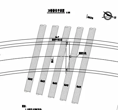
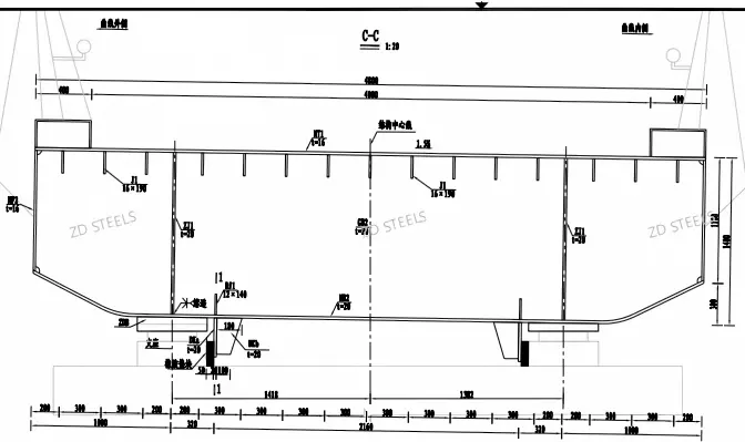
This is the No. 2 steel pedestrian overpass. The upper steel structure is a welded box girder in Q345qE, 131.2 t total. The C-C section shows a single box with edge cantilevers, internal diaphragms and vertical stiffeners; eight GBZY400×69(NR) bearings support the girder. The bridge centerline crosses the existing parallel strips and drainage ditches at a skew angle on the site plan.
Readable Section Data (C-C, 1:20)
| Item | Value |
|---|---|
| Overall deck width | 4,900 mm; inner top 4,000 mm; edge 400 mm |
| Bottom width | 1,000 + 2,160 + 1,000 mm |
| Section depth | 1,100 / 1,400 / 300 mm (upper / web / bottom zones) |
| Deck plate HT1 | t=16 |
| Outer web HF2 | t=16 |
| Internal diaphragm ZJ1 / GB2 | t=20 |
| Bottom plate HF2 | t=20 |
| Vertical stiffener J1 | 16 × 190 |
| Bearing stiffener | 12 × 140 |
| Deck cross fall | 1.5% |
| Curve side | Outside / inside marked on section |
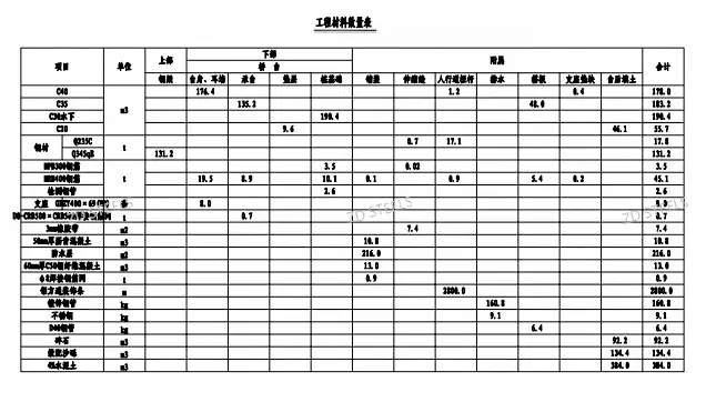
Main Material Quantities
表格
| Item | Grade / spec | Quantity | Unit |
|---|---|---|---|
| Steel girder | Q345qE | 131.2 | t |
| Railing / joint steel | Q235C | 17.8 | t |
| Bearing | GBZY400×69 (NR) | 8.0 | sets |
| C50 fiber concrete | 60 mm deck base | 13.0 | m³ |
| Asphalt concrete | 50 mm wearing course | 10.8 | m³ |
| Waterproof layer | — | 216.0 | m² |
| Welded mesh | D8-CRB500×CRB500 | 0.7 | t |
| Welded mesh | Φ8 | 0.9 | t |
| Rubber belt | 3 mm | 7.4 | m² |
| HRB400 rebar | — | 45.1 | t |
| HPB300 rebar | — | 3.5 | t |
| Galvanized railing pipe | — | 160.8 | kg |
| Stainless steel | — | 9.1 | kg |
| Aluminum square trim | — | 2,800.0 | m |
| D40 steel pipe | — | 6.4 | kg |
Substructure concrete: C40 178.0 m³, C35 183.2 m³, C30 underwater 190.4 m³, C20 55.7 m³; crushed stone 92.2 m³, graded sand-gravel 134.4 m³, 4% cement soil 384.0 m³.
How the Bridge Works
Box girder carries pedestrian load. The closed top plate, webs and bottom plate form a torsion-stiff box spanning between bearings.
Diaphragms and stiffeners hold the section. t20 diaphragms divide the box; 16×190 vertical stiffeners and the 12×140 bearing stiffener keep plate panels from buckling.
Bearings transfer reaction. Eight GBZY400×69(NR) bearings carry end and intermediate reactions to the substructure and allow controlled movement.
Deck build-up keeps the box dry. C50 fiber concrete base, waterproof layer, mesh and asphalt wearing course protect the steel top plate.
Skew alignment matches the site. The bridge centerline crosses existing strips at an angle; end diaphragms and bearings are set out from that centerline.
Advantages
Light steel superstructure — Q345qE box keeps dead load low for a pedestrian crossing, with shorter substructure works.
Closed box torsion stiffness — suits the skew crossing and asymmetric plan layout.
Protected steel deck — fiber concrete, waterproof and asphalt layers separate traffic wear from the steel plate.
Standard bearing and railings — NR bearings, galvanized pipe railings and aluminum trim are routine, replaceable parts.
Quantities are takeoff-ready — concrete, steel, mesh and finishes are itemized in the quantity table for procurement.
Disadvantages / Limits
Closed-box inspection — access hatches, drainage and ventilation must be arranged before the section is closed.
Skew fabrication — end plates, bearings and railing follow the skew angle; setting out must match the site centerline.
Deck waterproofing is critical — any leak reaches the top plate; the membrane and mesh must be continuous and protected before paving.
Stiffener and weld detail — web-to-diaphragm and bearing stiffener welds are fatigue-sensitive; toe grinding and NDT follow the detail.
Data gaps on these drawings — span, skew angle, pile diameter and length, and girder plate lengths are not listed here; capacity and weight takeoff need the original layout and BOM.
Typical Use Cases
Urban pedestrian overpasses crossing roads, railways or canals at skew angles.
Station, plaza and campus footbridges connecting separated pedestrian levels.
Park and greenway crossings where a clean shallow box fits the landscape.
Commercial complex link bridges with attached railings, lighting and trim.
Retrofit crossings where a lightweight steel superstructure speeds erection over live ground traffic.
Fabrication and Erection Notes
Verify Q345qE mill certificate; Q235C covers railing and expansion joint parts only.
Set out the box from the structure centerline; check the 4,900 mm deck width, 2,160 mm bottom width and 1.5% cross fall.
Fabricate t16 deck, t16 webs, t20 diaphragms and t20 bottom plate; fit 16×190 and 12×140 stiffeners per detail.
Mount the eight bearings to sole plates; check level and anchor fixings before launching.
Build the deck in sequence: C50 fiber concrete base, mesh, waterproof layer, asphalt; protect the membrane at edges and joints.
Complete railing, drainage and trim after alignment; inspect box interior access and drainage before handover.
Bottom Line
A Q345qE steel pedestrian overpass: 131.2 t welded box girder, 4.9 m wide, t16 deck and t20 bottom plate, eight GBZY400×69(NR) bearings, with a C50 fiber concrete and asphalt deck over 216 m² of waterproofing. The closed box handles the skew crossing; quantities and section plates come from the drawings, while span, skew angle and foundation details remain on the original bridge design.
**WhatsApp**: +86‑13889862778, +86‑18242444407
**Email**: eddie@zdsteels.com, wells@zdsteels.com
YOU MAY LIKE