
27 m Curved Pedestrian Bridge Steel Box Girder: Q345qE 131.2 t, 4.9 m Wide, Variable-Depth Section, 8 Bearings
2026-11-18 20:21:02






27 m Curved Pedestrian Bridge Steel Box Girder: Q345qE 131.2 t, 4.9 m Wide, Variable-Depth Section, 8 Bearings
English Version
Title: 27.0 m Pedestrian Overpass Box Girder — 131.2 t Q345qE, 4.9 m Deck Width, 600–1160 mm Variable Depth, Pre-Camber 41.7/38.1/41.7 mm
Data note: section plates, coordinates and quantities below are read from the A-A section, half-bridge plan, half-bridge elevation and the material quantity table. Lengths and plate dimensions are in mm; weights in tonnes. The girder steel is Q345qE; Q235C in the table covers railing and expansion joint parts only.
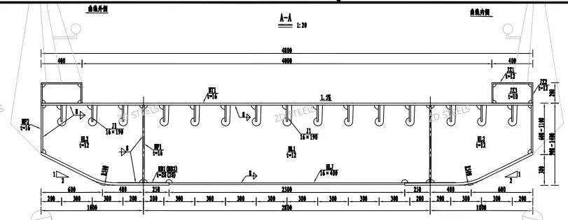
Overview
This is a welded steel box girder for a curved pedestrian bridge. The girder follows a 27.0 m centerline length (half 13.5 m) on a plan curve, with a single closed box and two edge boxes. Q345qE bridge steel totals 131.2 t for the upper steel girder. The deck carries a C50 fiber concrete base, waterproof layer and asphalt wearing surface; eight GBZY400×69(NR) bearings support the structure.
Girder and Bridge Data
| Item | Value |
|---|---|
| Bridge type | Curved pedestrian bridge, half shown in drawings |
| Centerline span length | 27,000 mm (half 13,500 mm) |
| Bottom half length | 12,280 mm per half (24,560 mm total) |
| Top deck width | 4,900 mm; inner top 4,000 mm; edge 400 mm each side |
| Bottom width | 1,000 + 2,800 + 1,000 = 4,800 mm |
| Box depth at A-A | Body 600–1,160 mm; lower haunch 248–1,400 mm; edge 200 mm; bottom 300 mm |
| Web batter | 1 : 2; corner radius R500 |
| Deck cross fall | 1.5% |
| Girder steel | Q345qE, 131.2 t |
| Bearings | GBZY400×69 (NR), 8 sets |
| Section scale | A-A 1:20; plan and elevation 1:40 |
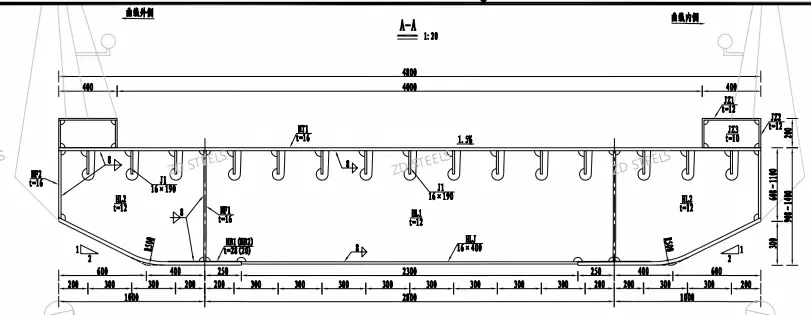
Section Plate List (A-A)
| Mark | Part | Thickness / size |
|---|---|---|
| HT1 | Deck plate | t=16 |
| HF1 | Inner web | t=16 |
| HF2 | Outer web | t=16 |
| HL1 | Bottom longitudinal plate | t=12 |
| HL2 | Bottom longitudinal plate | t=12 |
| JZ1 | Edge box top | t=12 |
| JZ2 | Edge box outer web | t=12 |
| JZ3 | Edge box inner plate | t=10 |
| J1 | Vertical stiffener | 16 × 190 |
| HLJ | Longitudinal stiffener | 16 × 400 |
| HF1(HF2) | Bottom plate | t=25 (t=20) |
End block and diaphragm plates in the elevation: ZJJ-1 / ZJJ-2 t=20, GB1 t=12, GB2 t=20, GB3 t=16, HB2 t=20.
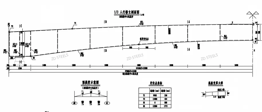
Geometry and Pre-Camber
Half-bridge elevation, measured along the structure centerline:
| Point | X coordinate (mm) | Z coordinate (mm) |
|---|---|---|
| T1 | 9,980 | 250 |
| T2 | 13,400 | 424 |
| B1 | 0 | 800 |
| B2 | 12,280 | 1,775 |
Pre-camber (developed along centerline): 41.7 mm at the 1/8 point, 38.1 mm at midspan, 41.7 mm at the 7/8 point. A plate-thickness change point is marked between two 900 mm panels.
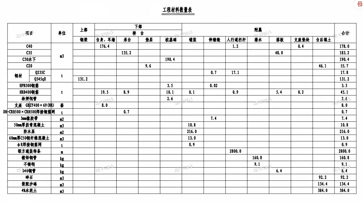
Material Quantities (selected)
| Item | Grade / spec | Quantity | Unit |
|---|---|---|---|
| Steel girder | Q345qE | 131.2 | t |
| Railing / joint steel | Q235C | 17.8 | t |
| Bearing | GBZY400×69 (NR) | 8.0 | sets |
| C50 fiber concrete | 60 mm deck base | 13.0 | m³ |
| Asphalt concrete | 50 mm wearing course | 10.8 | m³ |
| Waterproof layer | — | 216.0 | m² |
| Welded mesh | D8-CRB500×CRB500 | 0.7 | t |
| Welded mesh | Φ8 | 0.9 | t |
| Rubber belt | 3 mm | 7.4 | m² |
| Railing galvanized pipe | — | 160.8 | kg |
| Aluminum square trim | — | 2,800.0 | m |
How the Box Girder Works
- Closed box resists torsion. The single box carries vertical pedestrian load and the lateral effects of the plan curve; torsion stiffness comes from the four closed faces.
- Variable depth matches moment. The deeper haunch near the supports and the shallower midspan follow the bending diagram; deck and bottom plates stay efficient.
- Stiffeners hold plate panels. J1 verticals and HLJ longitudinal stiffeners prevent local buckling of the 12–16 mm plates between diaphragms.
- Edge boxes carry attachments. Side boxes integrate railing posts, drainage and trim without cutting the main box.
- Bearings transfer reaction. Eight GBZY400×69(NR) bearings distribute end reaction to the substructure and allow controlled movement.
Advantages
- High torsion stiffness for a curve — closed box performs better than an open plate girder on a curved alignment.
- Light weight for pedestrian loads — Q345qE box keeps dead load low while meeting bridge steel toughness requirements.
- Clean soffit line — variable-depth box reads neatly from below; edge boxes hide drainage and railings.
- Efficient section — depth and plate thickness follow moment; stiffener sizes are listed by position.
- Complete deck system — fiber concrete base, waterproof, asphalt and mesh are quantified in the table, ready for construction takeoff.
Disadvantages / Limits
- Inspection inside the box — closed cells need access hatches, drainage and ventilation planned before welding closes the section.
- Curved fabrication tolerance — webs, deck and bottom plates are set out from the centerline; curve offset and camber must be checked panel by panel.
- Haunch welding detail — variable-depth corners and R500 transitions need careful cutting and weld profiling.
- Fatigue detail control — deck-to-web and stiffener-to-web welds are fatigue-sensitive; toe grinding and NDT follow the bridge detail.
- Not a highway girder — this section is sized for pedestrian loads; vehicle load or wider deck would need a new design.
Typical Use Cases
- Urban pedestrian overpasses crossing roads, rail lines or waterways.
- Curved skybridges between buildings, stations or plaza levels.
- Park and greenway footbridges where a neat, shallow box fits the landscape.
- Campus and commercial complex link bridges with attached railings and lighting.
- Replacement or widened footbridges where lightweight steel speeds erection.
Fabrication and Erection Notes
- Verify Q345qE mill certificate and through-thickness and impact requirements before cutting.
- Set out panels from the structure centerline; apply the 41.7 / 38.1 / 41.7 mm pre-camber and the listed coordinates.
- Mark plate thickness zones: deck t16, webs t16, bottom t12, edge box t10–12, bottom plate t25(20).
- Weld diaphragms, stiffeners and end blocks per detail; inspect closed-cell welds before closure.
- Fit the eight bearings to the sole plates; check bearing level and anchor fixings.
- Erection: lift the curved box in planned segments, brace laterally before release, then complete deck waterproofing and paving.
Bottom Line
A 27.0 m curved pedestrian bridge steel box girder: 131.2 t Q345qE, 4.9 m wide, variable depth 600–1,160 mm, eight GBZY400×69(NR) bearings, with a C50 fiber concrete and asphalt deck. The closed box handles curve torsion; the variable depth follows the moment diagram. Section marks, coordinates and quantities come from the drawings; live-load capacity and substructure design remain on the original bridge design
**WhatsApp**: +86‑13889862778, +86‑18242444407
**Email**: eddie@zdsteels.com, wells@zdsteels.com
YOU MAY LIKE