
340.2 kg Independent Round-Tube Column: Φ219×12 Q235B Pipe, Haunched H Head Beam, 4 M20 Anchor Bolts
2026-11-18 20:13:49






340.2 kg Independent Round-Tube Column: Φ219×12 Q235B Pipe, Haunched H Head Beam, 4 M20 Anchor Bolts
English Version
Title: 340.2 kg Single Round-Tube Column GZ-2 — Φ219×12 Pipe, 2.882 m Long, H(180–272)×180×6×8 Head Beam on a 3.15 m Cap
Data note: all member specs, lengths and weights are read from the GZ-2 bill of materials and the 1-1 section. Weights are the BOM figures; the pipe unit weight below is derived at 7,850 kg/m³. Weld allowance is listed separately at 1.5%.
Overview
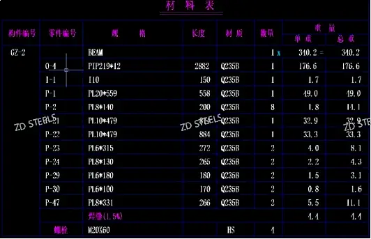
GZ-2 is one independent steel round-tube column. A Φ219×12 Q235B pipe forms the shaft; a welded tapered H beam branches left and right at the head; a base plate with radial stiffeners sits on a concrete cap and is fixed by four M20×60 high-strength bolts. Total weight of the member is 340.2 kg, one piece.
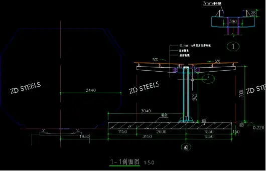
Readable Drawing Data
| Item | Value |
|---|---|
| Column mark | GZ-2 |
| Quantity | 1 pc |
| Total weight | 340.2 kg (incl. 4.4 kg weld allowance, 1.5%) |
| Shaft member | O-1, Φ219×12 round tube, L=2,882 mm |
| Shaft weight | 176.6 kg |
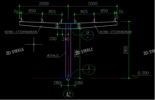
| Head beam | H(180–272)×180×6×8 welded tapered H, 2×2,000 mm sides |
| Base plate | P-1, PL20×559, L=558 mm, 49.0 kg |
| Bolt set | M20×60 high-strength bolt, 4 pcs, grade HS |
| Overall column height | 2,900 mm; clear shaft 2,526 mm |
| Head beam total width | 4,000 mm (2,000 + 2,000) |
| Base plate spread | 280 + 280 mm about axis A2 |
| Cap concrete | 3,150 mm wide, 150 mm thick; top level 0.220 |
| Top level | 0.300 |
| Roof finish | 0.6 mm profiled steel sheet, 5% dual-direction fall |
| Section scale | 1:50 |
Bill of Materials
表格
| Part | Spec | Length (mm) | Grade | Qty | Unit wt (kg) | Total wt (kg) |
|---|---|---|---|---|---|---|
| O-1 | Φ219×12 pipe | 2,882 | Q235B | 1 | 176.6 | 176.6 |
| I-1 | I10 | 150 | Q235B | 1 | 1.7 | 1.7 |
| P-1 | PL20×559 | 558 | Q235B | 1 | 49.0 | 49.0 |
| P-2 | PL8×140 | 200 | Q235B | 8 | 1.8 | 14.1 |
| P-21 | PL10×479 | 874 | Q235B | 1 | 32.9 | 32.9 |
| P-22 | PL10×479 | 884 | Q235B | 1 | 33.3 | 33.3 |
| P-23 | PL6×315 | 272 | Q235B | 2 | 4.0 | 8.1 |
| P-24 | PL8×130 | 265 | Q235B | 2 | 2.2 | 4.3 |
| P-29 | PL6×180 | 180 | Q235B | 2 | 1.5 | 3.1 |
| P-30 | PL6×100 | 170 | Q235B | 2 | 0.8 | 1.6 |
| P-47 | PL8×331 | 266 | Q235B | 2 | 5.5 | 11.1 |
| Welds | 1.5% allowance | — | — | — | 4.4 | 4.4 |
| Total | — | — | — | — | — | 340.2 |
Derived check: Φ219×12 tube weighs about 61.3 kg/m at 7,850 kg/m³; 2.882 m gives ≈176.6 kg, matching the BOM line.
Member Breakdown
| Function | Part | Description |
|---|---|---|
| Shaft | O-1 | Round hollow section carries axial load and moment |
| Head beam | H(180–272)×180×6×8 | Tapered welded H, two cantilever sides, supports purlins/roof |
| Base plate | P-1 PL20×559 | Distributes shaft load to the cap |
| Stiffeners / cleats | P-2, P-21, P-22, P-23, P-24, P-29, P-30, P-47 | Node plates and radial ribs around shaft and head |
| Small section | I-1 I10 | Short connection cleat, 150 mm |
| Anchor | 4×M20×60 HS | Fixes base plate to concrete cap |
How the Column Works
Shaft takes axial force and moment. The round tube carries vertical load; its closed section resists local buckling better than an open angle or channel.
Head beam branches to the roof. The tapered H beam spans left and right; depth grows toward the column where moment is highest.
Base plate spreads the reaction. PL20×559 transfers shaft force into the cap; stiffeners keep the plate from bending under the column.
Anchor bolts hold uplift and moment. Four M20×60 high-strength bolts resist tension and shear at the base; the cap must be designed for the same reaction.
Advantages
Clean round shaft — a circular tube reads neatly in open-side sheds and canopies; no exposed angle toes.
Good axial and buckling behavior — closed CHS section handles compression with favorable radius of gyration.
Single-column layout — one post per support point leaves interior space free of knee bracing.
Integrated head beam — the welded H branch carries roof purlins directly, one column-to-roof node.
Standard sections — Φ219×12 tube, I10 cleat and plate sizes are common stock; fabrication is straightforward.
Disadvantages / Limits
Closed tube hides interior corrosion — sealed ends can trap moisture; ends need sealing, venting and internal coating where specified.
Base design carries the moment — plate, bolts and cap must resist lateral load; a weak foundation limits the column.
Node fit-up matters — tube-to-H-head and tube-to-plate welds need angle cuts and jigs to keep the shaft plumb.
Lateral stability comes from the roof — an independent post cannot stand alone in wind; roof bracing and purlin ties are required.
Tapered H fabrication — depth changes 180–272 mm along the cantilever; web cutting and flange rolling must follow the detail.
Typical Use Cases
Single-story industrial sheds and workshops where interior bracing would block layout.
Entrance canopies and gate posts needing a neat round exposed column.
Open-side warehouses and loading bays with unobstructed floor space.
Equipment platforms and pipe-rack support posts.
Parking sheds and small-span awning frames on independent bases.
Fabrication and Erection Notes
Material: Q235B; check mill certificate against the BOM.
Cut the Φ219×12 shaft to 2,882 mm; verify straightness and end square.
Weld the PL20×559 base plate and radial stiffeners first; keep the shaft vertical on the jig.
Assemble the tapered H head beam; match the 180–272 mm depth profile and the 180 mm flange width.
Use the four M20×60 high-strength bolts at the base; do not substitute ordinary bolts without design approval.
Seal tube ends, apply the specified corrosion protection, and connect roof bracing before releasing the temporary support.
Bottom Line
GZ-2 is a 340.2 kg independent round-tube column: Φ219×12 Q235B shaft, tapered welded H head beam, PL20×559 base plate, four M20×60 anchor bolts. It suits open-side sheds and canopies where a single clean post carries the roof branch. Capacity and foundation reaction still depend on the original structural design; this article covers the member data on the drawing.
**WhatsApp**: +86‑13889862778, +86‑18242444407
**Email**: eddie@zdsteels.com, wells@zdsteels.com
YOU MAY LIKE