
37 m Twin-Deck Box Girder: 2200 mm Depth, 3-Cell Section on a 2.49% Expressway Grade
2026-11-17 19:02:14






37 m Twin-Deck Box Girder: 2200 mm Depth, 3-Cell Section on a 2.49% Expressway Grade
English Version
Title: 37 m-Wide Twin-Deck Box Girder Bridge — 17.8 m Single Deck, 2.2 m Box Depth, Three-Cell Section for a Curved Expressway Route
Drawing note: dimensions below are read from the plan, I-I section and E-E section. Main girder steel grade, plate thicknesses, pile diameter and pile length are not stated on these screenshots; confirm against the original bridge design drawings before fabrication or quotation.
Overview
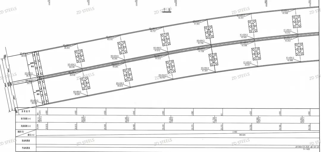
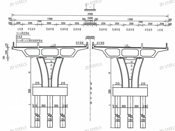
This is a twin-deck box girder expressway bridge. The plan runs from station K0+874.5 to K1+054.5, on a 2.490% grade over 390.926 m, inside a horizontal curve of R=1420 m. The I-I section shows two separated decks; the E-E section shows one deck as a three-cell closed box. Each deck carries sidewalk, non-motorized lane and motorized lanes, with a C50 fiber concrete pavement and asphalt wearing surface.
Readable Drawing Data
| Item | Value on drawing |
|---|---|
| Layout | Twin decks, central gap 2×500 mm |
| Total deck width | 37,000 mm |
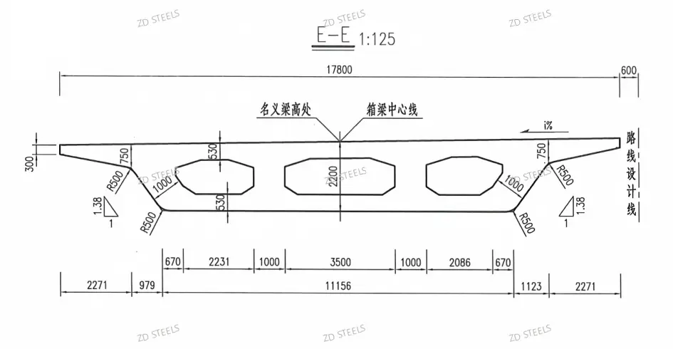
| Single deck width | 17,000 mm (I-I); E-E overall 17,800 mm, cantilever 600 mm |
| Box nominal depth | 2,200 mm |
| Cells per deck | 3 cells |
| Inner box width | 11,156 mm |
| Slab dimensions | Top / bottom slab 530 mm; edge depth 750 / 300 mm |
| Web batter | 1.38 : 1; corner radius R500 |
| Deck cross slope | 1% (E-E); 1.5% (I-I) |
| Pavement | 90 mm asphalt concrete, waterproof layer, 80 mm C50 polyacrylonitrile fiber concrete |
| Grade | 2.490%, grade length 390.926 m |
| Horizontal curve | R=1420 m, deflection -54°24′, JD at K0+731.3531 |
| Bent stations | K0+874.5 → K1+054.5 |
| Design elevation range | 38.771 m → 43.253 m |
| Piers | Y-shaped pier, cap beam 200, three-pile foundation; pile layout 110+300+300+110, pile Ø120 (units per original detail) |
Deck Cross-Section (I-I)
| Band, one side | Width (mm) | Function |
|---|---|---|
| Outer curb | 500 | Edge / drainage |
| Sidewalk | 2,000 | Pedestrian |
| Non-motorized lane | 3,500 | Cycles / slow traffic |
| Motorized lanes | 3,500 + 3,250 + 3,250 | Main traffic |
| Mirror band | Repeated on opposite deck | — |
Pavement build-up from top: 90 mm asphalt concrete → waterproof layer → 80 mm C50 polyacrylonitrile fiber concrete.
Box Section (E-E, scale 1:125)
Three closed cells; box centerline and nominal depth point marked on the drawing.
Bottom width segments: 2,271 + 979 + 670 + 2,231 + 1,000 + 3,500 + 1,000 + 2,086 + 670 + 1,123 + 2,271 mm.
Webs lean at 1.38:1; internal and external corners use R500.
Top slab falls at 1% toward the route design line.
Route Data
| Station | Design level (m) | Ground level (m) |
|---|---|---|
| K0+874.5 | 38.771 | 35.694 |
| K0+904.5 | 39.318 | 35.610 |
| K0+934.5 | 40.265 | 35.550 |
| K0+964.5 | 41.012 | 35.430 |
| K0+984.5 | 41.759 | 35.370 |
| K1+024.5 | 42.506 | 35.310 |
| K1+054.5 | 43.253 | 35.190 |
The bridge crosses above existing ground; embankment heights widen toward the K1 end.
How the Box Girder Works
Closed box resists torsion. Three cells share load across the 17.8 m deck; the box section keeps torsional distortion low on the curved alignment.
Slabs carry wheel loads. Top slab distributes axle loads to the webs; bottom slab closes the section and carries tension under positive moment.
Webs carry shear. Inclined webs transfer panel shear down to the piers; R500 corners reduce stress concentration.
Separate decks divide traffic. Twin decks separate directions and slow traffic from motorized lanes; the central gap leaves space for barrier and utilities.
Advantages
Wide deck in one box — a multi-cell box carries heavy highway traffic with a clean, shallow-looking underside.
High torsion stiffness — closed section performs well on the R=1420 m curve and under eccentric vehicle load.
Low wind profile — deep box with sloped webs suits expressway viaducts where open truss would catch more wind.
Separated traffic layout — sidewalk, non-motorized and motorized lanes fit on two decks with barrier separation.
Standard pavement build-up — asphalt over C50 fiber concrete and waterproof layer is a routine expressway deck detail.
Disadvantages / Limits
Section weight — a three-cell solid box is heavier than a steel truss or plate girder of the same span; foundations must match the dead load.
Site access inside the box — inspection, drainage and maintenance inside closed cells need access hatches and ventilation planned early.
Curved fabrication — webs, slabs and soffit follow the R=1420 m alignment; segment geometry must be set out from the centerline.
Data gaps on these screenshots — girder steel grade, plate thicknesses, span length, pile diameter and pile length are not legible here; capacity and quantity takeoff need the original drawings.
Waterproofing is critical — deck leakage into the box shortens slab and web life; the waterproof layer must be continuous and protected before paving.
Typical Use Cases
Urban expressway viaducts — separated decks for through traffic over ground-level roads.
Curved approach bridges — R=1420 m alignment where a torsion-stiff box is preferred.
Multi-lane road bridges — sidewalk plus non-motorized lane on each deck.
Elevated crossings over existing roads or drainage — elevated box on bent piers.
Corridor links and interchange ramps — box sections that fit a sloping, curved alignment.
Fabrication and Erection Notes
Confirm girder material, plate/slab thickness and weld or concrete specification against the original design.
Set out each segment from the box centerline; check the 1.38:1 web batter and R500 corners before assembly.
Place bent centers at the plan stations; verify cap beam and pile layout against the foundation detail.
Build the pavement in sequence: fiber concrete base, waterproof layer, asphalt wearing course; protect the membrane.
On erection, brace segments before release; check elevation and cross slope at each support.
Bottom Line
A 37 m twin-deck box girder for a curved expressway: 17.8 m-wide decks, 2.2 m nominal depth, three cells, C50 fiber concrete and asphalt pavement. The closed box handles torsion on the R=1420 m curve and carries mixed traffic on separated decks. Material grades, thicknesses, spans and pile data come from the original bridge drawings — this set of screenshots does not list them.
**WhatsApp**: +86‑13889862778, +86‑18242444407
**Email**: eddie@zdsteels.com, wells@zdsteels.com
YOU MAY LIKE