
Steel Box Girder Lifting Lugs: Design Data and Functions
2026-11-03 13:00:00






Steel Box Girder Lifting Lugs: Design Data and Functions
English Version
Title: Steel Box Girder Lifting Lugs: R33 Hole, 0.7 t Each — What They Do and How They're Built
Overview
A lifting lug (padeye) is a steel plate welded to a box girder so the crane can pick the girder up. It is not a permanent structural member — it exists for one phase: lifting, transporting, and erecting. But a lug that fails during the lift drops the whole girder, so its geometry, welds, and steel grade get real engineering attention.
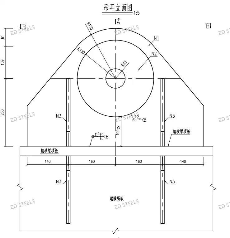
The drawings show the lugs used on this project's steel cross girders: a plate lug welded to the top flange and end diaphragm, with a φ66 lifting hole and a reinforced outer profile.
Drawing Data
| Item | Value (from drawing) |
|---|---|
| Drawing | Lifting lug elevation, scale 1:5 |
| Lifting hole | R33 (φ66 mm) |
| Outer profile | R130 / R170 (two-radius reinforced edge) |
| Lug plate mark | N3 |
| Connections | Welded to steel cross girder top flange + end diaphragm |
| Welds | N1, N2 (marked on drawing) |
| Bolt holes | p4 × φ12 |
| Plate sizes | 61 / 109 / 230 (height), 140 / 160 (width) |
| Steel grade | Q345qE / Q345qENH |
| Weight per project set | 1.32 t (shop drawing) → 0.675 t (revised design) |
What the Lug Does
1. Lifting point. The crane hook (or shackle) passes through the R33 hole. The lug transfers the full girder self-weight plus rigging load into the box girder.
2. Turning and flipping. During fabrication, lugs are used to roll, flip, or tilt the girder for welding and painting positions.
3. Transport lashing. Lugs serve as tie-down points when the girder is strapped on a trailer or barge.
4. Temporary support. Paired lugs on the top flange allow spreader-beam lifting with two or four points, keeping sling angles safe.
Design Logic Shown in the Drawing
R33 hole with R130/R170 profile: the double radius spreads the bearing stress around the hole edge. A single sharp edge would tear under point load.
Welded to top flange + end diaphragm: the load path runs from lug plate → flange → diaphragm, so the girder web is not punched by local force.
N3 plate, N1/N2 welds: the lug is a dedicated plate mark with its own weld callouts — full-penetration or fillet per the drawing, checked with NDT.
p4 bolt holes: bolt holes allow a temporary erection plate or shackle pin retainer; also used to bolt on a protective cap after lifting.
Q345qE / Q345qENH: bridge-grade steel with guaranteed low-temperature toughness — important because lifting often happens in cold weather.
Advantages
One-piece plate lug is cheap — cut from plate, welded in minutes; no machining needed beyond drilling the hole.
High capacity for its weight — 0.7 t of lug steel can safely lift a 100+ t box girder.
Reusable on site — after erection, lugs can be cut off, ground flush, and the area weld-repaired and repainted.
Multiple lift points — a pair of lugs gives a stable two-point lift with a spreader beam, no sling angle problems.
Inspectable before lift — welds and hole edge are visible; MT/UT can be done on site before the critical lift.
Disadvantages / Limitations
Not a permanent member — lugs must be removed or flame-cut after erection; leftover stubs and weld marks need grinding and touch-up paint.
Local stress concentration — the load goes into one small zone of the flange; the diaphragm and stiffeners under the lug must be checked, or the plate deforms.
Weld quality is everything — a cold weld or slag inclusion under the lug fails at full load; NDT before the lift is mandatory, not optional.
Lifting angle limits — a lug is designed for a vertical or near-vertical sling. Side pull beyond the design angle overloads the lug plate and can bend the hole.
Fire and coating damage — flame-cutting lugs off damages the shop coating; the repair zone needs full recoating per the paint system.
Typical Use Cases
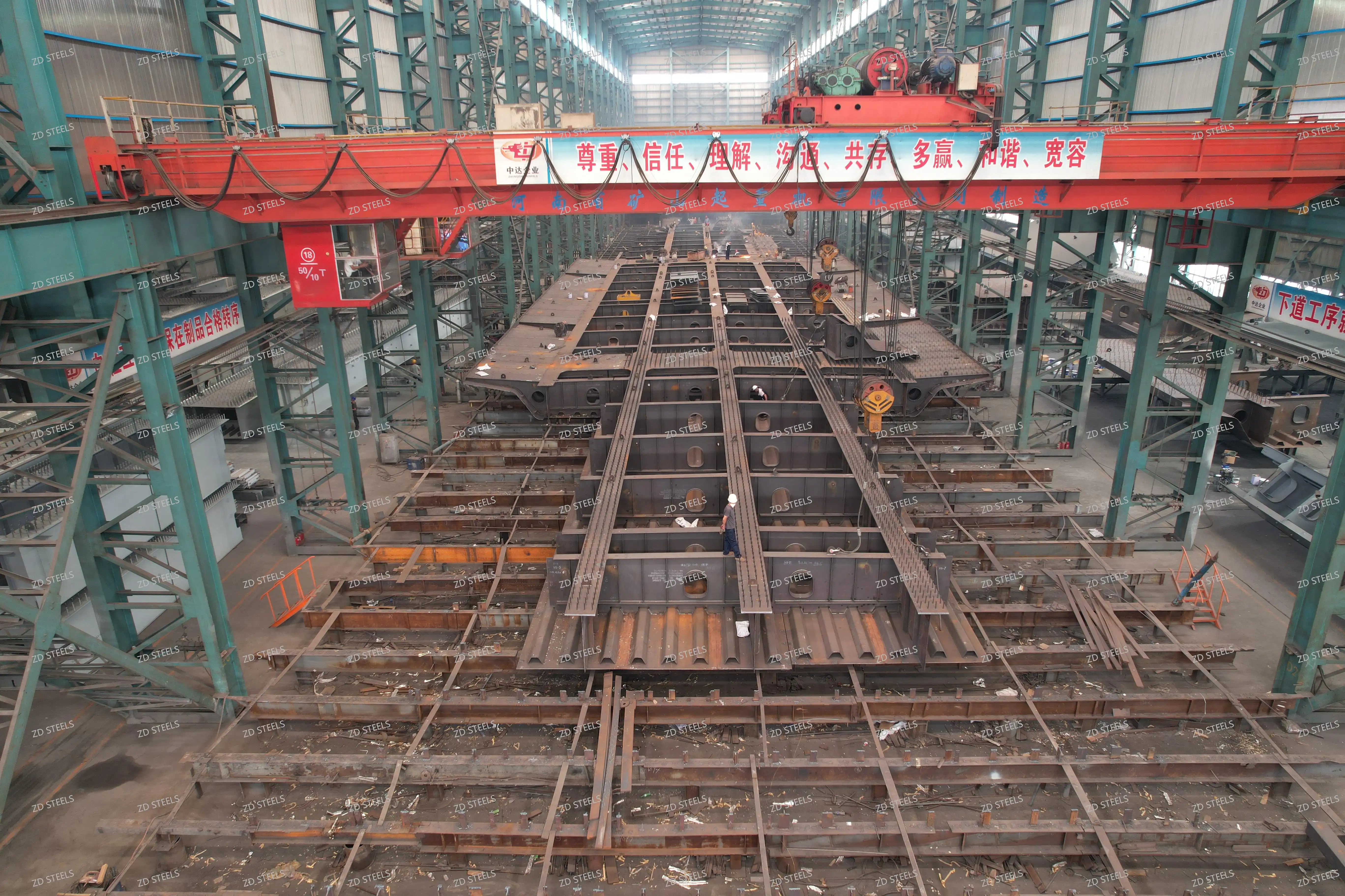
Steel box girder erection — lugs on the top flange for crane lifts during bridge erection (the case in these drawings).
Girder flipping in the workshop — lugs let a 200 t box girder be rolled and turned for welding and blasting positions.
Railway bridge steel cross girders — lifting lugs on cross girders and diaphragms, as shown in the project material table.
Transport and lashing — lugs as tie-down points on trailers, rail wagons, and barges.
Temporary structures — lifting lugs on formwork supports, falsework, and erection steel where pick points are needed.
Fabrication and Lifting Notes
Confirm the steel grade mill certificate: Q345qE / Q345qENH per GB/T 714 for bridge service.
Weld lugs with N1/N2 per the drawing; preheat per plate thickness; check welds with MT or UT before the lift.
Match the hole to the shackle pin: φ66 hole takes a standard 55 t-class shackle (pin ~60 mm); verify clearance before rigging.
Use a spreader beam for two-point lifts; keep the sling angle ≥60° from horizontal.
After erection: flame-cut the lug, grind flush, repair the weld zone, and recoat per the specified paint system.
Never lift with a lug that shows deformation at the hole, cracked welds, or paint damage around the weld zone.
Bottom Line
A box girder lifting lug is a small, cheap plate that carries the entire lift. The drawings show the essentials done right: a φ66 hole with radiused edge, welded to the flange and diaphragm, in bridge-grade steel with weld inspection. Design it, weld it, check it — and the girder goes up safely. Cut it off, grind it flush, and the bridge looks as if the lug never existed.
**WhatsApp**: +86‑13889862778, +86‑18242444407
**Email**: eddie@zdsteels.com, wells@zdsteels.com
YOU MAY LIKE