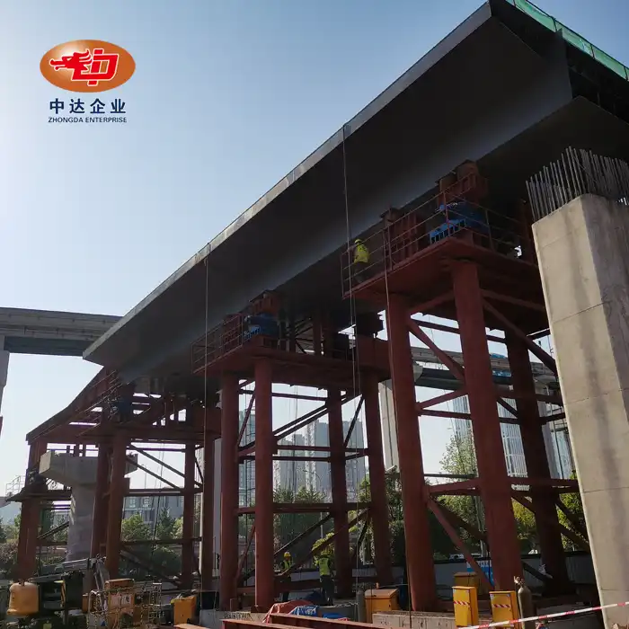
Long-Span Steel Box Girder Incremental Launching






2. Material: Q345D main (≥345MPa), Q420D for joints.
3. Customization: Variable cross - section (1.25 - 8m), 20% weight reduction, 420m span.
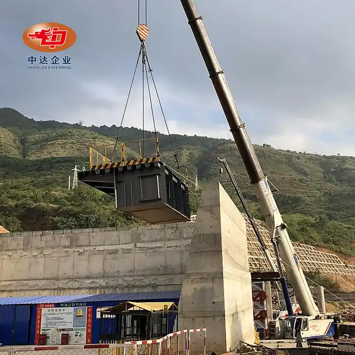
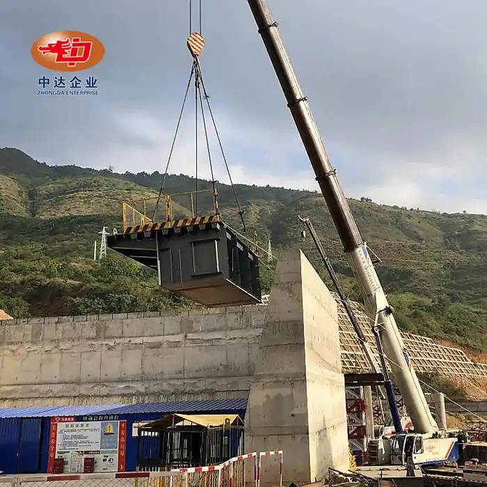
4. Construction: Prefabrication (12 - 30m), on - site assembly, 50% time reduction.
5. Anti - Corrosion: Double (galvanizing or spraying), ≥32 years service.
Long-Span Steel Box Girder Incremental Launching: Enterprise-Grade Bridge Construction Solutions
When your project demands rapid bridge deployment over active rail corridors or environmentally sensitive waterways, Long-Span Steel Box Girder Incremental Launching delivers unmatched efficiency. At Shenyang Zhongda Steel Structure Engineering Co., Ltd., we use precision 3-axis CNC drilling (±0.1mm tolerance) and Q345D high-strength steel to build fully-welded steel box girders with a proven span capacity of 420 meters. With controlled 12-30m segment manufacturing in our 75,000m² ISO 9001-certified plant, our integrated prefabrication system cuts on-site building time by 50%. Our sophisticated automated welding lines and 80,000-ton yearly capacity enable us to assist big EPC contractors, such as China State Construction and China Railway Group, on infrastructure projects with tight deadlines.
Product Description
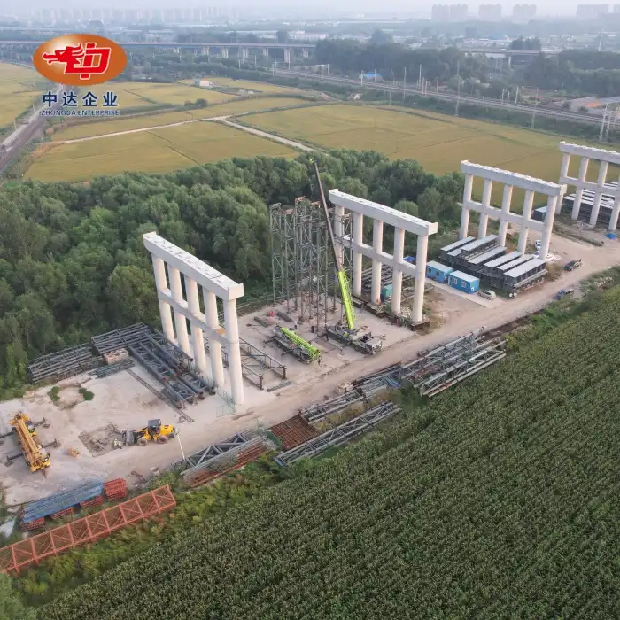
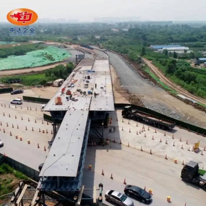
Incremental launching transforms how you build bridges in challenging environments. This methodology assembles steel box girder segments at a fixed casting yard behind the abutment, then progressively pushes them across piers using synchronized hydraulic jacks. You eliminate expensive falsework, bypass traffic disruptions, and maintain continuous construction over obstacles.
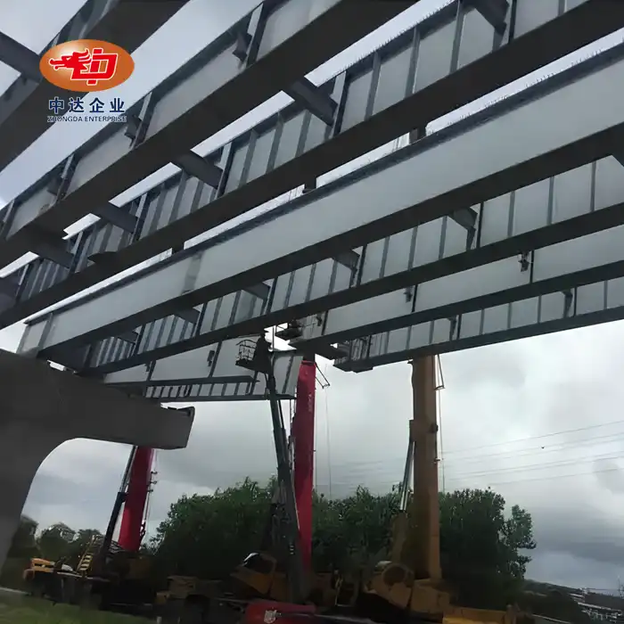
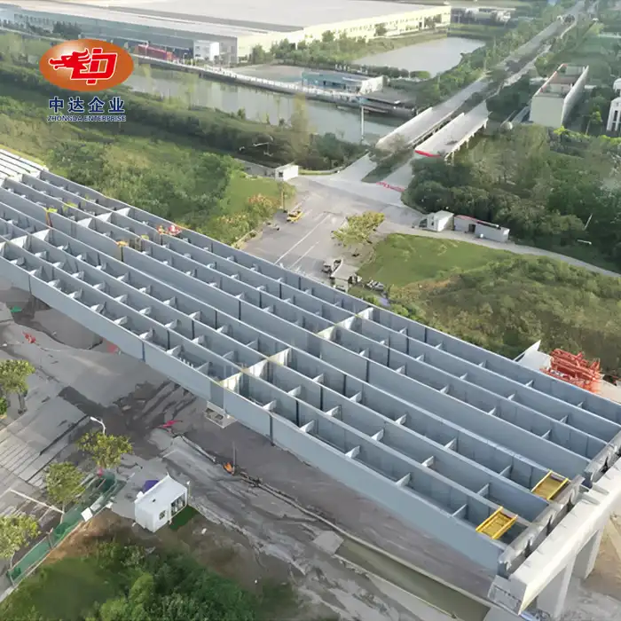
Our steel box girders feature fully-welded monocoque construction. This closed-cell design offers superior torsional rigidity compared to I-beams. The streamlined profile naturally resists lateral wind loads—critical for long-span applications.
The launching process relies on specialized low-friction PTFE sliding systems. These achieve friction coefficients between 0.03-0.05, drastically reducing required thrust forces. A lightweight launching nose—typically 60-70% of your maximum span length—extends ahead of the girder to minimize cantilever moments during push cycles.
Temperature monitoring is essential. We integrate real-time strain gauges and 3D laser scanning at 500mm intervals. This ensures your alignment stays within ±2mm tolerances throughout the launch sequence, even when crossing multiple piers.


Product Advantages
Traffic Zero-Impact Construction
You keep highways and railways fully operational. The launching method builds above existing infrastructure without lane closures or train schedule modifications. This preserves regional logistics networks and eliminates costly traffic management plans.
Superior Factory Quality Control
Welding happens in our climate-controlled workshops, not on exposed piers. You get consistent penetration, proper preheating, and 100% Phased Array Ultrasonic Testing on every joint. Field weld quality risks simply disappear.
Accelerated Project Schedules
Parallel workflows change everything. While your foundation contractor installs piers, we're already fabricating girder segments. The assembly-launch cycle operates 24/7 in controlled conditions. Projects finish 50% faster than conventional methods.
Environmentally Sensitive Deployment
Cross protected wetlands without temporary piling. Span deep channels without marine equipment. The self-launching system uses the bridge's own structure as the construction platform, leaving zero ecological footprint below.
Weight-Optimized Engineering
Our variable cross-section design tapers girder depth from 8m at piers to 1.25m at midspan. This achieves 20% mass reduction versus constant-depth designs. You lower material costs, reduce pier loads, and simplify foundation requirements.
Enhanced Structural Durability
Factory-applied double protection systems—hot-dip galvanizing plus epoxy topcoats—deliver ≥32-year service life. The sealed box cross-section prevents internal moisture accumulation and corrosion initiation at hard-to-inspect locations.
Technical Specifications & Customization
|
Parameter |
Standard Range |
Custom Capabilities |
|
Maximum Span Length |
40-120m per segment |
Up to 420m total bridge length with temporary pylons |
|
Girder Height Range |
1.25m - 8.0m (variable section) |
Optimized per span-to-depth ratio (typically 1:20 to 1:25) |
|
Girder Width |
10m - 16m |
Custom multi-cell configurations for wide decks |
|
Primary Steel Grade |
Q345D (≥345MPa yield) |
Q420D for high-stress joints, Q500 for ultra-long spans |
|
Segment Length |
12m - 30m |
Determined by transportation clearance and crane capacity |
|
Launching Nose Weight |
60-70% of maximum span load |
Carbon fiber composite options for extreme weight reduction |
|
Friction Coefficient |
0.03 - 0.05 (PTFE/SS systems) |
Hydrostatic bearing systems for friction <0.01 |
|
Alignment Tolerance |
±2mm horizontal/vertical |
Real-time correction via adjustable sliding bearings |
|
Welding Standards |
AWS D1.5, EN 1090-2 Class EXC3 |
Fatigue-rated Category B details for dynamic loads |
|
Corrosion Protection |
Galvanizing + epoxy (DFT ≥200μm) |
Marine-grade systems (C5-M) with zinc-rich primers |
|
Production Capacity |
80,000 tons annually |
Expedited schedules for emergency infrastructure |
|
Plate Thickness Range |
Up to 300mm ultra-thick processing |
CNC flame/plasma cutting for complex geometries |

Manufacturing & Quality Control
Advanced Fabrication Infrastructure
Our 120,000m² facility houses 1200-ton plate rolling machines and 50-ton overhead cranes. CNC cutting systems handle ultra-thick plates up to 300mm. Three-axis CNC drilling ensures bolt-hole precision within 0.1mm—critical for field assembly tolerances.
Four-Stage Quality Protocol
Stage 1: Material Verification
Every steel coil undergoes Mill Test Certificate validation and independent tensile testing. Charpy V-notch impact tests at -20°C confirm toughness for welded bridge applications.
Stage 2: Weld Integrity Inspection
We perform 100% Phased Array Ultrasonic Testing (PAUT) on longitudinal butt welds. Magnetic Particle Inspection (MPI) detects surface discontinuities in all tension zones. Acceptance criteria exceed AWS D1.5 Category B requirements.
Stage 3: Geometric Control
Continuous 3D laser scanning monitors camber and sweep during assembly. BIM-integrated software compares as-built geometry against design models in real time. Deviations trigger immediate corrective action before welding proceeds.
Stage 4: Launch Monitoring
We install strain gauges on girder webs and launching noses to verify stresses remain below 70% yield strength. Load cells on sliding bearings measure pier reaction forces. PLC systems synchronize multi-jack displacement to within ±1mm, preventing torsional binding.
International Compliance
Our management systems hold ISO 9001 (quality), ISO 14001 (environmental), and ISO 45001 (safety) certifications. Products comply with EN 1090 (EU), AWS D1.1/D1.5 (USA), and JIS standards (Japan). Full documentation packages include MTCs, NDT reports, and English technical drawings for global projects.
Project Cases
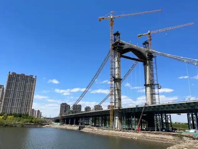
Shenyang Dongta Cross-Hunhe River Bridge
This 18,000-ton landmark project demonstrated our heavy bridge engineering capability. The crossing required continuous construction over active shipping lanes without marine scaffolding. Our incremental launching system completed the 380m main span in 14 months—40% faster than the client's original schedule. Variable-depth box girders reduced steel consumption by 2,200 tons while meeting stringent deflection limits under highway truck loads.
Jingha Expressway Expansion Projects
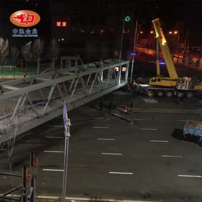
Multiple overpass bridges demanded zero-disruption construction above 8-lane expressway traffic. Using Long-Span Steel Box Girder Incremental Launching, we assembled 25m segments in roadside yards and launched them during brief nighttime windows. The self-supporting method eliminated temporary piers in traffic lanes. All 12 bridges achieved geometric tolerances within ±1.5mm, enabling direct deck placement without field adjustments.

Compliance & Certifications
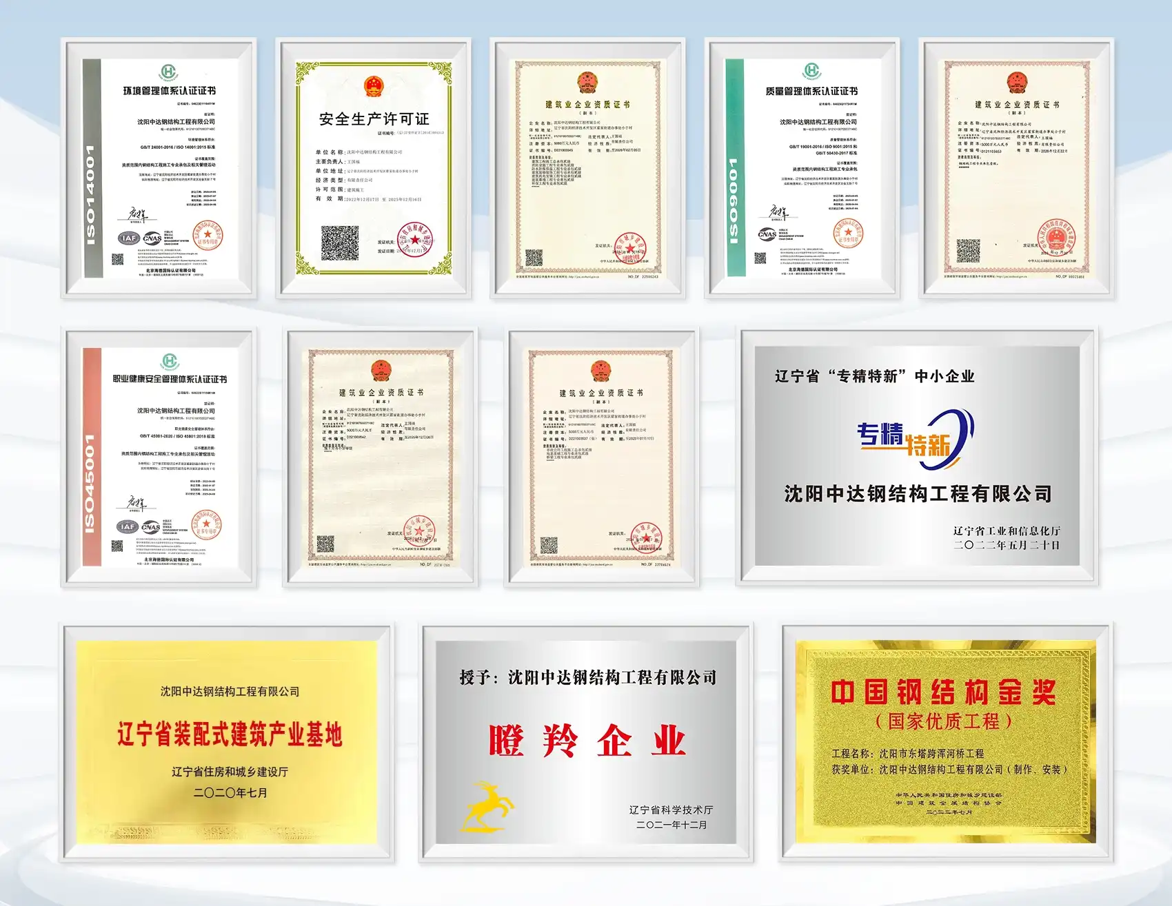
· ISO 9001:2015 Quality Management System
· ISO 14001:2015 Environmental Management System
· ISO 45001:2018 Occupational Health & Safety
· EN 1090-2:2018 Execution Class EXC3 for Steel Structures
· China Steel Structure Association Member Enterprise
· Class I Steel Structure Professional Contracting Qualification
· National High-Tech Enterprise Status (since 2004)
· Liaoning Province Key Prefabricated Building Base
We maintain compliance with AWS D1.5 (Bridge Welding Code) and provide full traceability documentation for international EPC projects, including Belt and Road Initiative infrastructure programs.
Frequently Asked Questions
Q: What is the maximum span length you can achieve with this method?
A: While 40-70m segments are standard, we've successfully launched spans exceeding 120m using temporary stay pylons and optimized launching nose designs. The 420m bridge length represents our longest completed project to date.
Q: How do you manage temperature effects during launching?
A: Temperature gradients cause vertical deflection in long girders. We schedule alignment checks during stable-temperature windows (typically nighttime) and integrate thermal compensation factors into our hydraulic PLC control systems.
Q: What if friction coefficients exceed design limits?
A: Our system triggers automatic shutdown if thrust forces indicate abnormal friction. Technicians then inspect sliding interfaces for debris or pad wear, clean surfaces, and reapply silicone-based lubricants before resuming operations.
Q: Can this method work for curved bridge alignments?
A: Yes, provided the curve maintains constant radius. We install specialized side-guide rollers to manage centrifugal components of launching forces. Horizontal alignment monitoring increases to every 300mm intervals on curved projects.
Q: How is multi-jack synchronization controlled?
A: A centralized Master-Slave PLC system governs all hydraulic jacks. Position sensors provide real-time feedback, ensuring displacement synchronization within ±1mm. This prevents torsional binding and uneven pier loading during the push cycle.
Q: What's your typical lead time for a 100m span project?
A: From engineering approval to first segment launch: approximately 4-5 months. This includes 2 months for detailed shop drawings, 2 months for segment fabrication, and 1 month for launching system installation and testing..
Contact Us
Ready to address tough project difficulties for Long-Span Steel Box Girder Incremental Launching and other complex bridge construction scenarios? Our engineering team provides free feasibility assessments and custom design proposals tailored to your site conditions.
Get Your Project Quote Today Ava@zd-steels.com
YOU MAY LIKE